- Mobile NO: +91 98336 40613
- Send Your Mail At: sales@adfastcomponents.com
Menu
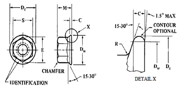
| Nominal Nut Diameter and Thread Pitch | Width Across Flats, S | Width Across Corners, E | Flange Diameter, Dc, Max | Bearing Circle Diameter, Dw, Min | Flange Edge Thickness, C, Min | Thickness, M, | Flange Top Fillet Radius, R, Max | |||
|---|---|---|---|---|---|---|---|---|---|---|
| Max | Min | Max | Min | Max | Min | |||||
| M5 x 0.8 | 8.00 | 7.78 | 9.24 | 8.79 | 5.10 | 4.80 | 6.9 | 3.2 | 2.9 | 2.0 |
| M6 x 1 | 10.00 | 9.78 | 11.55 | 11.05 | 5.70 | 5.40 | 8.9 | 3.5 | 3.2 | 2.4 |
| M8 x 1.25 | 13.00 | 12.73 | 15.01 | 14.38 | 7.50 | 7.14 | 11.6 | 4.4 | 4.1 | 2.9 |
| M10 x 1.5 | 15.00 | 14.73 | 17.32 | 16.64 | 10.0 | 9.60 | 13.6 | 5.7 | 5.4 | 3.4 |
| M10 x 1.5 | 16.00 | 15.73 | 18.48 | 17.77 | 9.30 | 8.94 | 14.6 | 5.2 | 4.9 | 3.4 |
| M12 x 1.75 | 18.00 | 17.73 | 20.78 | 20.03 | 12.00 | 11.57 | 16.6 | 7.3 | 6.9 | 4.0 |
| M14 x 2 | 21.00 | 20.67 | 24.25 | 23.35 | 14.10 | 13.40 | 19.6 | 8.6 | 8.0 | 4.3 |
| M16 x 2 | 24.00 | 23.67 | 27.71 | 26.75 | 16.40 | 15.70 | 22.5 | 9.9 | 9.3 | 5.3 |
| M20 x 2.5 | 30.00 | 29.16 | 34.64 | 32.95 | 20.30 | 19.00 | 27.7 | 13.3 | 12.2 | 5.7 |
| M24 x 3 | 36.00 | 35.00 | 41.57 | 39.55 | 23.90 | 22.60 | 33.2 | 15.4 | 14.3 | 6.7 |
| M30 x 3.5 | 46.00 | 45.00 | 53.12 | 50.85 | 28.60 | 27.30 | 42.7 | 18.1 | 16.8 | 8.5 |
| M36 x 4 | 55.00 | 53.80 | 63.51 | 60.79 | 34.70 | 33.10 | 51.1 | 23.7 | 22.4 | 8.5 |
All dimensions are in millimeters.